Lessons on: UPS Configurations
In Part 1 we learned about the different UPS topologies. This time we’ll focus on UPS configurations. How are topologies different from configurations you ask? Good question.
UPS topology is what goes on inside the UPS. The UPS configuration is how it is connected to the outside world, i.e. its inputs, outputs, and bypass. In addition, the configuration describes the way redundant UPS modules are interconnected to provide continuous unintinterrupted power to the critical load.
Before I get started, I need to provide some clear terminology so that the discussion will begin to make sense.
- UPS Topology
- The inner workings of the UPS module that permit the uninterrupted flow of power to the critical load.
- UPS Module
- The single cabinetized package that accepts one sert of inputs, and provides one set of outputs.
- UPS System
- Two or more UPS modules interconnected to provide uninterrupted power to the critical load.
- UPS Bypass or Static Bypass
- The means provided within a UPS module or a UPS System to instantaneously (within 4ms) transfer to an alternate input source so as to maintain power to the critical load.
There are five basic configurations:
- Single Module (non-redundant)
- Multi-module Parallel (non-redundant)
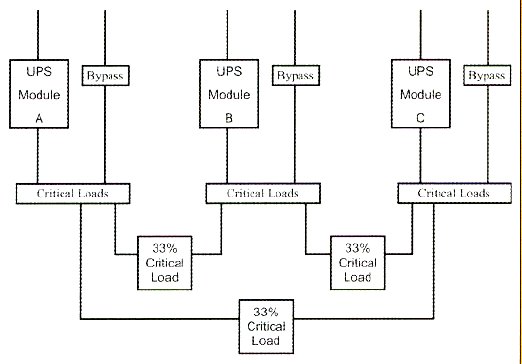
- Segmented Redundant
- Multi-module Parallel Redundant
- Multi-module Shared Redundant
A single module system is very popular in small and medium data centers that need conditioned power but don’t need high reliability or continuous availability. No redundancy means a downtime hit of at least once per year for normal preventative maintenance activities. This is very economical and simple and used to serve 90% of UPS installations. Today, critical environments cannot afford annual downtime for maintenance.
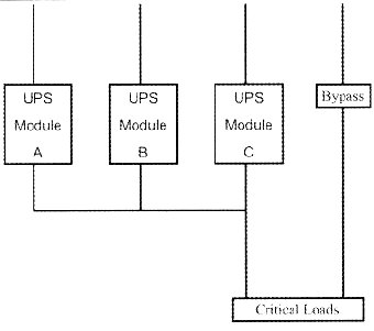
A multi-module parallel system is similar in concept to a single module system, but requires more modules because the critical load is too big for just one module…typically anything over 800 to 1,000kva will rquire more than one module. The modules are typically connected to together on the output side to provide a single bus for the critical load distribution. The units provide power in a parallel fashion, much as a team of horses pulls a stage coach or wagon together. This requires special load-sharing technology so that all modules will share an equal portion of the load so that no one module is overloaded and trips off line. With no redundancy, this configuration suffers the same problem with annual maintenance downtime, and is therefore not a very reliable solution.
A segmented redundant configuration splits up the load into “segments” that are individually supplied by a single UPS module, but whose internal bypass is connected to a redundant UPS. This configuration provides much better reliability than the first two, but require identification of which loads to separate. A challenge with this system, is that it can only handle a first order failure, since when the redundant module is being eplyed in backing up a failed module, it is unavailable for any further maintenance or failure-based downtime of the other modules.
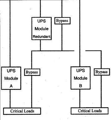
A multi-module parallel redundant system is similar to the multi-module non-redundant system except that an additional module is plugged into the bus to allow total flexibility (any source to any load) should a UPS module fail or require repair. The disadvantage most often sited for this configuration is that the output paralleling current can be so high that standard bus-sizing is not an option.
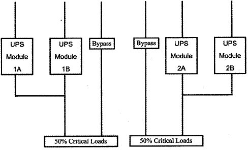
A system plus system UPS configuration is very inefficient but very reliable. The system is basically a double system that provides both component redundancy and system redundancy. The challenge with this system is that it takes a great deal of space and coordination to provide multiple paralleling synchronization schemes.
Finally, a shared redundant system seeks to improve efficiency but maintain operational reliability and optimum uptime. The concept here is to provide some additional capacity in each UPS System so that it can pick up a portion of the load – but not all – from the other aspects of the active UPS system.